Acorn BBC Master Compact Joystick
Comments and questions about this article are welcome on the Stardot Forums thread: What *CONFIGURE PROPORTIONAL, SWITCHED and STICK actually do on the Master Compact.
The Acorn BBC Master Compact was the last in the line of 6502-based 8-bit BBC Microcomputer models, coming after the acquisition of Acorn Computers by Olivetti. While it was the first BBC Micro to include a disc-drive as standard, the computer itself was an exercise in value engineering and size reduction to fit in a case which came from the same mould as the ill-fated Acorn Communicator. Many of the external interfaces which made earlier Beebs so expandable and flexible were omitted. The connectors of some remaining ports such as the disc and printer ports were changed, perhaps to fit the new case design, but breaking compatibility with existing peripherals.
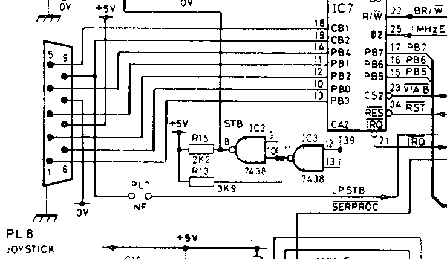
In particular, the analogue port of the Model A/B and Master 128, which was backed by an NEC µPD7002 analogue to digital converter (ADC) and exposed as a female DA-15 connector (with active-low fire button support provided by PB0 and PB1 from the System VIA) has been deleted. In its place, the Master Compact exposes a male DE-9 connector labelled Joystick / Mouse. Internally, this port is wired to lines PB0 to PB4 of the User VIA (IC7). In addition, User VIA lines CB1 and CB2 are exposed, which together with +5 V power and 0 V ground account for all nine pins. The CB1 and CB2 lines can be used to trigger interrupts and so are useful for interfacing to the rapidly toggling quadrature signals produced by a mouse.
Physically, the Compact’s Joystick/Mouse connector is wired to be compatible with the Atari Joystick pinout, using pins 1 to 4 for the direction signals and pin 6 for the fire signal. These signals are active-low, so the switches pull the signals down to 0 V when activated. Neither the positive supply line (pin 7) nor the two paddle lines (pins 5 and 9) are used by Atari-compatible switched joysticks.

Atari games paddles (each paddle is a single-axis rotary game controller such as one might use for playing Pong or Breakout – hence ‘paddle’) place one variable resistor for each paddle (500 kΩ) between the +5 V supply (pin 7) and the respective paddle inputs on pins 5 and 9. The corresponding CB1 and CB2 lines on the Compact are digital lines, so while Atari switched joysticks will work, Atari paddles will not.
Moreover, while the Master Compact Mouse/Joystick port is an Atari compatible joystick port, it is not an Atari compatible mouse port; the Atari mouse pinout, while also a DE-9 connector, is quite different to that needed by the Compact. Use of a mouse on the Master Compact deserves another article, suffice to say that due to overlapping pin allocations, the port on the Compact is either a joystick port or a mouse port, and cannot be used for both as the same time with any kind of passive adapter.
On the software side, there is a lot of new and different code in Acorn MOS 5.x to handle the replacement of an analogue joystick interface connected to the System VIA by a digital joystick interface connected to the User VIA. These changes to the operating syatem make a best effort to maintain compatibility with existing software which uses official APIs, abstracting away the hardware differences.
There are also new joystick-specific configuration commands like *CONFIGURE PROPORTIONAL, *CONFIGURE SWITCHED and *CONFIGURE STICK which have always been poorly documented; documentation which certainly doesn’t do justice to what lies within. In fact, the documentation is so bad that reviewers of the Master Compact writing for magazines in 1986 often got completely the wrong end of the stick about the meaning of terms like proportional in this context:
... for the Compact, Acorn has elected to support the switch-type joystick, along with the mouse and trackerball. This is done by providing an "industry-standard" joystick/mouse port, with a 9-pin D socket — as used by Atari and Commodore, amongst others. The operating system software allows the new port to accept either "switched" (joystick) or "proportional" (mouse) inputs.
-- Gordon Taylor writing the cover story Master Compact Exposed. Acorns New Machine. for A&B Computing, October 1986
Having recently annotated the relevant parts of Tom Seddon’s disassembly (and reassembly) of the Acorn Master-series MOS I’m now able to explain how what these options do, how to use them correctly, and to draw back the veil on a surprisingly sophisticated and yet misunderstood part of Acorn MOS 5.x.
The ADVAL interface
To work with existing software which expects a joystick on the analogue port, MOS 5.x provides new code behind the existing operating system interface for interacting with the analogue subsystem. The most important of these interfaces is OSBYTE &80 (128) Read ADC channel. The ADVAL function in BBC BASIC is essentially a high-level wrapper around OSBYTE &80. The ADVAL function accepts a channel number, and this is passed to OSBYTE &80 in the X register.
Despite its name, the Analogue Digital VALue function serves multiple other purposes when passed a non-positive value. For negative channel values ADVAL and OSBYTE &80 obtain the number of items in various operating system buffers, such as the keyboard buffer, RS423 serial buffers, the printer buffer, and the sound channel buffers.
Reading Joystick Switch and Button States
For channel zero, OSBYTE &80 returns two pieces of information. In the X register it returns the state of various switches (buttons is too specific a term) and in the Y register it returns the number of the most recently updated analogue channel. At the BBC BASIC level, the X and Y register values are presented as the lo- and hi-bytes respectively of a single 16-bit integer. The BBC User Guide for the Model B shows how to extract the parts separately using,
buttons% = ADVAL(0) AND 3to mask for the bit 1 and bit 0 to extract the left and right fire button states. Whether these were the fire buttons of separate primary and secondary joysticks wired into the same plug (like the Voltmace Delta 3B Twin), or separate buttons on the same joystick (like the Voltmace Delta 3B Single) depends entirely on the joystick hardware.
Note that OSBYTE &80 inverts in software from the active-low hardware signals to positive logic, so a 1 here represents ‘pressed’. Prior to MOS 5.x, OSBYTE &80 also performs AND 3 to mask for bit 1 and bit 0 (the other bits contain state from other internal hardware connected to the System VIA), so extracting the whole lo-byte with,
buttons% = ADVAL(0) AND &FFgives the same result.
The Master Compact is a bit different because the joystick interface supports only a single fire button in bit 0, so,
buttons% = ADVAL(0) AND 1is sufficient to extract that state.
In MOS 5.x, OSBYTE &80 does not perform an AND 3 operation to mask for the lower bits and so returns the whole byte intact. What does it contain? Bits b7 to b4 contain the four direction switch states right, up, down and left (hence my preference for the term ‘switches’ over ‘buttons’ earlier). Bits b3 to b1 are set aside in the documentation for three mouse button states right, middle and left. Other than this tacit allocation, there is no support in MOS 5.x for the mouse or its buttons. I don’t know whether these bits are set by the Master Compact mouse driver or not; I haven’t investigated it yet. So, all the switch states can be extracted with,
buttons% = ADVAL(0) AND &FFand then individual joystick switch states with,
right% = buttons% AND &80
up%    = buttons% AND &40
down%  = buttons% AND &20
left%  = buttons% AND &10
fire%  = buttons% AND &01
In versions prior to MOS 5.x, the contents of the Y register returned by OSBYTE &80 – and so the hi-byte of the value returned by ADVAL(0) – contains the number of the last analogue-to-digital converter channel to be read. On the Master Compact the value is always 2 and is essentially a meaningless vestigial value.
All switched joystick state on the Master Compact can be obtained through channel zero with OSBYTE &80 with X = 0 or ADVAL(0). However, all software written before MOS 5.x expects joystick axis information be obtained through channels one and two for the primary joystick, and channels three and four for the secondary joystick.
Joystick Deflection: Simulating Analogue Values
On BBC Micros with real analogue hardware prior to MOS 5.x, the non-negative ADVAL channel assignments are as follows, returning results from the analogue-to-digital converter:
| Channel | Joystick Convention |
|---|---|
| 1 | Primary joystick x-axis |
| 2 | Primary joystick y-axis |
| 3 | Secondary joystick x-axis |
| 4 | Secondary joystick y-axis |
| >4 | Always returns max values |
The values from the converter scaled to 16-bit unsigned value in the range 0–65535 with a midpoint at 32767. In hexadecimal these are &0000–&FFFF with the midpoint at &7FFF. It’s important to know the sense of these quantities.
The x-axis (horizontal) which increases to the left, has the opposite sense to screen coordinate convention:
| left | centre | right |
|---|---|---|
| &FFFF | &7FFF | &0000 |
The y-axis (vertical) has the same sense as screen coordinate convention:
| down | centre | up |
|---|---|---|
| &0000 | &7FFF | &FFFF |
Switched Joystick Mode
On the Master Compact with MOS 5.x and only digital joystick hardware these extreme and centre values are exactly what you get if you set MOS into switched joystick mode using,
*CONFIGURE SWITCHED
Not that you’d be able to determine this from reading the hopeless Welcome Guide for the Master Compact. Under its explanation of *CONFIGURE switched it says,
*CONFIGURE SWITCHED- Configure cursor-key simulation of joysticks to produce limited range of values.
needlessly conflating one MOS feature (cursor key joystick simulation) with another (mapping direction switch states to integer ADVAL values). Moreover, limited range conveys the wrong idea; it results in a limited number of values over the full range.
We’ll return to the topic of cursor key simulation of joysticks later.
Proportional Joystick Mode
The complement of SWITCHED is apparently PROPORTIONAL. Let’s be generous to the technical writers and not dwell on the fact that the SWITCHED values are also proportional to the stick position, albeit on a very coarse scale.
So, what does *CONFIGURE PROPORTIONAL do? How can this possibly make sense on a machine with only hardware support for switched joysticks? For guidance we can turn to the Welcome Guide, which says,
*CONFIGURE PROPORTIONAL- Configure cursor-key simulation of joysticks to produce full range of values.
Setting aside misdirection regarding the cursor keys, and having established that SWITCHED also produces values across the full range, albeit limited in number, how are we to interpret this? It’s hard to know from the manual alone. After three days analysing and commenting the relevant sections of the disassembly of the Master-series MOS, I was able to figure out the surprisingly sophisticated routine which the Compact uses to convert instantaneous digital switch states into smoothly varying 16-bit ADVAL channel values that simulate analogue joystick deflection. I haven’t seen this described elsewhere and suspect I may be one of very few people other than the original author to understand not only how this feature works internally, but how it behaves at the user level.
The digital joystick handling routine is polled at 100 Hz. In PROPORTIONAL mode, the code uses an integration algorithm to convert instantaneous digital switch states for the joystick directions into smoothly varying 16-bit ADVAL channel values that simulate analogue joystick deflection. The algorithm implements linear acceleration where, starting from the centre position, the rate of change of the ADVAL value is proportional to the duration of time for which the stick has been pushed in a consistent direction. This rate of change is capped though, so after a certain amount of time the rate of change of ADVAL stays constant. Eventually, the ADVAL value itself reaches its limit at &0000 or &FFFF and there can be no further decrease or increase.
The rate at which the rate of change of ADVAL grows (i.e. second derivative with respect to time) is not only a function of how long the stick has been held in a consistent direction, but also the ‘rate’ setting supplied by *CONFIGURE STICK. Referring to the Welcome Guide again:
*CONFIGURE STICK n- Set joystick acceleration rate in PROPORTIONAL mode to n (0–7)
This is undoubtedly the most illuminating of the three joystick-related *CONFIGURE descriptions in the manual. Even so, it contains an inaccuracy (which we will come to shortly) and fails to mention an interesting secondary effect of the rate value.
The essence of the analogue joystick emulation is as follows:
-
Each polling tick increments a counter
while a consistent direction is held. Note that this 8-bit counter saturates at &FF (255) and has code to stop it wrapping to zero. -
The channel value increment is calculated as
where is the elapsed time for which a consistent direction has been held, and is the rate 1–7. -
This produces quadratic growth. The simulated proportional deflection (ADVAL value) increases (or decreases) as the square of elapsed time
-
When the most-significant byte (MSB) of the increment exceeds the configured rate value, velocity limiting activates.
-
The velocity limit is programmed as
, producing linear growth thereafter, however long the joystick is held in that direction. -
Rate 1 can never reach its programmed velocity limit. There isn't enough time before the counter
saturates at &FF (255). However, counter saturation also has the effect of limiting the velocity, albeit at a lower slightly lower level of &FF (255) than the programmed level &0101 (257). -
When the stick is returned to the centre position (no direction switches active) the counter
resets. Notably, the ADVAL channel value holds or coasts at its current value, so further joystick input in the opposite direction will be required to return to the centre value. In practice, returning to and staying at the exact centre value of &7FFF is likely to be quite difficult, unlike in SWITCHED mode.
It can be hard to build intuition for how this works from the code or a written description. Some charts should help. The first charts show the response of an ADVAL channel to switched up/down commands. The stepped red line shows the joystick direction input encoded as either up, centre or down. The blue curve shows the response of the ADVAL channel, illustrating how the value changes exponentially as the stick is held in a consistent direction, but coasts at a constant value when the stick is centred. Further stick inputs are required to return the ADVAL channel value to close to the centre value.

The lower chart shows the signed instantaneous increments in green, which are a function of the counter value (pale grey) and the sign of the switch input. The blue curve in the upper chart is the integral of the green sawtooth in the lower chart. These charts show behaviour that stays within both the limits inherent in the 16-bit ADVAL quantity and the various programmed limits.
The next chart shows how the various limiting behaviours further modify the ADVAL response. The channel value starts at its minimum of zero, and then when the joystick changes from down to up (effectively instantaneously) the counter is reset and the ADVAL channel enters a domain of quadratic growth caused by the increment added at each time step growing linearly in size each time. At 0.38s after accelerated started, the velocity reaches the rate 7 limit of &0707 (1799) and so the ADVAL channel enters a period of linear growth. At 0.5 seconds after the change in joystick input the maximum channel value of &FFFF (65535) is attained.

The Stick Rate Setting
In PROPORTIONAL mode, the rate set by *CONFIGURE STICK controls not only the responsiveness, but also the maximum acceleration rate of the ADVAL value. From an extreme position, at rate 7 (the fastest) maximum simulated deflection to the other extreme will occur in 0.50 seconds. At rate 1 (the slowest) full-scale deflection will occur after 3.84 seconds. Only rates 7, 6 and 5 experience velocity limiting in practice. For rates 4, 3 and 2 the ADVAL channel saturates at &FFFF (65535) before the velocity limits take effect. Rate 1 is again becomes limited to linear growth, but for a quite different reason: After 255 centisecond clock ticks (2.55 s) the one-byte counter saturates at &FF (255) and thereafter the increment can grow no more, rendering the growth of the ADVAL channel value linear.

Ultimately, the rather clever system of rate limits shown below, only takes effect for the fastest three of the seven rates, owing to the other limitations described above.

Not that you would know from reading the Welcome Guide, but rate 0 is special, and causes the effective rate to be set to 3. Rates of 8 and above can also be supplied, but these will be clamped back to a rate of 7.
Multi-modal inputs from joystick and keyboard
As alluded to by the guide for *CONFIGURE SWITCHED and *CONFIGURE PROPORTIONAL, and buried in the documentation for the *FX commands (i.e. OSBYTE calls) are some other joystick-related features of MOS 5.x.
Edit Keys Simulating Joystick
The olive-drab coloured edit-keys (cursor keys and COPY key) can be configured to simulate a joystick by issuing a *FX4,3 command. The 3 here is one of the four available cursor editing modes, and the only one unique to MOS 5.x. In this mode, the cursor keys drive the joystick simulation according to the prevailing SWITCHED or PROPORTIONAL setting.
In SWITCHED mode pressing left cursor key ADVAL(1) immediately jumps to &FFFF. As soon the key is released ADVAL will return to the centre value of &7FFF, giving the same auto-centring response as a real switched joystick.
In PROPORTIONAL mode when pressing the left cursor key ADVAL(1) begins integrating towards &FFFF according to the configured rate and duration of keypress. The longer you hold, the further it goes, with first quadratic and then, after velocity limiting kicks in, linear growth. Releasing the key holds ADVAL at the current value, and the right cursor key must be used to reduce the value again.
Interestingly, in *FX4,3 “joykeys” mode, the input from the joystick port is still processed. The result from the keyboard is combined with the result from the joystick using a logical-OR, meaning that both the keyboard and joystick inputs are respected.
This raises the question of what happens in the event of conflicting signals. The mechanical construction of a switched joystick ensures that activation of opposing direction switches is mutually exclusive, but the cursor keys alone or in combination with the joystick afford no such constraint. In SWITCHED mode left ($FFFF) takes precedence over right (&0000), and down (&0000) takes precedence over up (&FFFF), so if all four directions are activated this is interpreted as the joystick being in the bottom-left position. The difference in sense between the horizontal and vertical axes here seems arbitrary and is controlled by the ordering of an internal table used to convert switch activations to ADVAL values. It seems likely that given the mechanical constraints of real joysticks that this wasn’t given much consideration. On the other hand, bottom-left is the graphics origin and so perhaps it’s a deliberate design decision. Only the original programmer will know how much consideration went into the table ordering.
In PROPORTIONAL mode conflicting switch or key activations cause the ADVAL value to stay effectively constant as an increment and an immediately following decrement will cancel out, giving the same effect as having no switch activations.
To disable, “joykeys” mode issue *FX4,0 to restore normal edit-key behaviour.
Joystick Simulating Edit Keys
As well as being able to use the cursor keys to emulate a joystick, the reverse is also possible: The joystick can be used to emulate the cursor keys. This mode is activated with OSBYTE &BE (190) with X=64, or *FX190,64 at the command line. In this mode the ADVAL(1) and ADVAL(2) values are not updated by the joystick. Instead, the contents of the ADVAL(0) lo-byte which contains the switch status bits are used to drive keyboard-like actions. The joystick direction bits cause simulated key presses of the cursor keys, and the bit 0 fire button becomes the equivalent of pressing the COPY key, making it possible to drive the cursor around the screen and copy text using the joystick alone. Curiously, the activation of bits 1, 2 and 3 of this byte cause COPY, RETURN and DELETE respectively to be ‘typed’. These bits are associated – in the documentation at least – with three mouse or trackball buttons.
In all cases, the keyboard simulation is pretty faithful to the real thing, including auto-repeat delays, and so on. That said, the joystick simulation of edit keys runs one centisecond tick behind updating of the ADVAL values. The button states read by this routine are those emplaced on the previous tick, so there is an inherent 10 ms delay in the conversion of joystick input to simulated key presses.
When Modes Collide
You may have noticed that *FX4,3 and *FX190,64 can be set independently, which means they can be set simultaneously. Simultaneous emulation of the joystick by the edit keys and the emulation of the edit keys by the joystick! What then?! There’s nothing in the MOS 5.x code to prevent this situation, and the design of the joystick routine doesn’t obviously take this scenario into account.
If both are enabled the joystick hardware and edit keys are scanned and logically OR-ed together as per edit-keys simulate joystick mode. Their combined state ends up in the ADVAL(0) lo-byte. Then the joystick simulates edit-keys routine picks up the ADVAL(0) lo-byte and converts it back to an edit-key press, which goes into the keyboard buffer. Normally, in *FX4,0 mode (the default) putting these codes into the keyboard buffer would initiate edit mode if necessary and move the secondary cursor around. But we’re in *FX4,3 mode, so the edit-key code in keyboard buffer is ignored, preventing a positive feedback loop. The net result is that neither cursor movement not simulated ADVAL analogue channel updates occur. The two modes cancel each other out, rendering both features inactive.
Analogue Software and Hardware Extensibility
MOS 5.x is unique among the MOS variants in providing an extensibility mechanism specifically for replacing the built-in handling of ADVAL channels, by instead invoking sideways ROM service call &2C. The only part of the joystick system not replaceable by this call is the simulation of edit keys by the joystick; if enabled this will continue to run one tick behind switch state result emplacement, regardless of whether the switch states are set by the built-in joystick routine or a replacement in a service ROM.
Joystick service call delegation is enabled by setting bit 7 of the OSBYTE &BE (190) parameter X. The most straightforward invocation from the command line is *FX190,128 but this resets all other bits in the ADVAL configuration byte to zero, wiping out the bits which control the built-in MOS ADVAL handling. Use *FX190,128,127 which will set the top bit to enable the service call and preserve the 7 lower bits. To disable the service call and restore built in joystick handling with the prior configuration, use a *FX190,0,127 command.
A joystick service ROM needing a few bits for storage of configuration could use bits 3 and 4 of the configuration byte, as these are otherwise unused by MOS 5.x. In principle, a ROM could also repurpose the six bits from bit 0 to bit 5 as these are only used by the built-in joystick routine, though there is the potential for confusion caused by the overloading of semantics and the fact that the *CONFIGURE SWITCHED, PROPORTIONAL and STICK, and their *FX equivalents will continue to affect these bits.
Sadly, there is no *CONFIGURE option for enabling or disabling the joystick ROM service call, though the equivalent bit is stored in the non-volatile RAM and it could, in principle, be directly manipulated to enable the ROM service call across hard resets and power cycles. By implementing sideways ROM service calls &28 (unknown CONFIGURE) and &29 (unknown STATUS) it should be possible to add such a facility along with other persistent configuration pertaining to a custom ADVAL driver.
The full details of how to implement a Sideways ROM service call are beyond the scope of this article, suffice to say that a routine servicing call &2C will receive in the Y register the offset into page 2 of the ADVAL workspace, always &B6, which is to say that the ADVAL workspace is always at address &02B6 in MOS 5.x (and indeed in earlier versions of the Master MOS, though there’s no reason in principle that it couldn’t be elsewhere in page 2). This workspace comprises 8 bytes laid out as follows:
| Address computation | Address | Purpose |
|---|---|---|
| &0200 + Y + 0 | &02B6 | Switch state byte |
| &0200 + Y + 1 | &02B7 | ADVAL(1) LSB |
| &0200 + Y + 2 | &02B8 | ADVAL(1) MSB |
| &0200 + Y + 3 | &02B9 | ADVAL(2) LSB |
| &0200 + Y + 4 | &02BA | ADVAL(2) MSB |
| &0200 + Y + 5 | &02BB | Available |
| &0200 + Y + 6 | &02BC | Available |
| &0200 + Y + 7 | &02BD | Available |
This workspace layout is specific to MOS 5.x. The arrangement of the first five bytes is mandated by the design of OSBYTE &80 (128) which expects to find the results for channels 0, 1, and 2 laid out like this, so conforming service call implementations must use these workspace entries for the results they want to see returned for these channels. This also means that the service call mechanism does not support extensibility beyond channel 0 for switches and analogue channels 1 and 2.
MOS 3.x uses a different layout for the workspace allowing for ADVAL channels 1 to 4, and in any case does not support service call &2C for analogue system extensibility. In MOS 3.x the ADVAL(0) state is not stored in the workspace – it’s pulled directly from System VIA input register B.
ROM extensions which wish to accommodate analogue hardware with more channels will need to intercept the BYTEV vector to override the default implementation of OSBYTE &80 allowing you to return ADVAL results in an arbitrary, either reinterpreting the bytes of the workspace to be more like the MOS 3.x layout (see below) or doing something else altogether.
The Mertec Companion was a hardware expansion which attached to the 50-way expansion connector of the Master Compact to add variety of interfaces, including a Beeb compatible analogue port. This used a µPD7002 (just like the other Beebs) connected to the system bus through a 68B21 Peripheral Interface Adapter (PIA), a similar device to the 6522 VIAs used in the BBC Micro. As it provided four analogue channels, The Mertec Companion ROM hooked into BYTEV, probably to replace OSBYTE &80.
Conclusion
The Master Compact’s digital joystick system exemplifies the value engineering philosophy of the machine: clever software compensating for cost-reduced hardware while maintaining backwards software compatibility. Eliminating an expensive µPD7002 analogue-to-digital converter chip and supporting circuitry will have reduced parts cost by between £5 to £10 at mid-1980s volume prices. It will have saved space on the printed circuit board helping the Compact fit in the case design it inherited from the Acorn Communicator, and simplified assembly somewhat.
The sophistication of the proportional mode algorithm with its integration, velocity limiting and smooth quadratic to linear transition is particularly remarkable given how much it was undersold by the accompanying documentation. Acorn programmers made a sterling effort to make digital joysticks feel surprisingly like analogue controls, yet the official documentation failed to explain what it actually did or how to use it effectively.
The keyboard-to-joystick and joystick-to-keyboard mappings demonstrate thoughtful design improving usability and perhaps making some games accessible to even to those without a joystick or unable to use one. Sadly, their documentation was somewhat scattered through the Welcome Guide, rather than being gathered in the section about adding a joystick.
Some design choices remain puzzling. The inverted X-axis inherited from earlier MOS versions going back to the Model A/B. Is this just a historical accident arising from the wiring of the first joystick? Then there’s the vestigial “last channel read” value, which is always 2, and the somewhat arbitrary conflict resolution precedence, though the coincidence with the bottom-left graphics origin is intriguing.
Perhaps little of this matters now beyond its curiosity as an artefact to be studied by us software archaeologists. (As a contributor the inaugural, and to-date only, edition of The International Conference on Software Archaeology (TICOSA) held in London in 2014, it’s an interest I’ve long held.). Retro-computing enthusiasts delight in understanding the decisions and forces that resulting in their favourite machines, warts and all. The few but talented contemporary 8-bit BBC Micro game developers might be minded to take the Compact’s capabilities into account, but this probably mostly affects players of games on the Master Compact. The Compact is arguably the most convenient of the real Beebs for those who wish limit the amount of desk space we concede to this hobby and I hope that a better understanding of Acorn MOS support for its joystick system will enable better use to be made of it.
After nearly four decades of obscurity, the Master Compact’s joystick handling code can finally be appreciated for what it is: a sophisticated piece of systems programming that deserves better than it got from the original documentation.
Reference
The following commands persist in the non-volatile RAM and survive reboots. They take effect immediately and set the default state on start-up:
*CONFIGURE SWITCHED- Enable switched joystick mode. Direction changes from the joystick (or keyboard, if enabled with
*FX4,3) cause joystick deflection as measured through ADVAL channels 1 and 2 to jump immediately to minimum (&0000), centre (&7FFF) or maximum (&FFFF) values. The values are auto-centring, so in the absence of left/right or up/down input the channel values will revert immediately to their centre values. *CONFIGURE PROPORTIONAL- Enable proportional joystick mode (default). Direction changes from the joystick (or keyboard, if enabled with
*FX4,3) cause simulated joystick deflection as measured through ADVAL channels 1 and 2 to accelerate smoothly in that direction at a rate set by*CONFIGURE STICKor*FX190,<rate>. In the absence of directional input, the simulated analogue value channels will hold at their current value. *CONFIGURE STICK <n>- From 1 to 7 the value of
is the rate at which the simulated proportional joystick deflection accelerates. High rates make the system more responsive. Lower rates give better control. For equal to 0, the rate will be set to 3. For above 7, the rate will be clamped to 7. The rate can also be set by *FX190,<rate>
The following command take effect immediately, but do not persist across hard resets:
| CLI | OSBYTE | Effect | ||
|---|---|---|---|---|
| A | X | Y | ||
*FX190,<rate> |
&BE (190) | rate 0–7 | 0 | Set STICK rate temporarily. Implicitly enables PROPORTIONAL mode (clears bit 5 of X). Values from 8 to 31 will be clamped to rate 7, but also set otherwise unused bit 4. |
*FX190,32 |
&BE (190) | &20 (32) | 0 | Enable SWITCHED mode (sets bit 5 of X) |
*FX190,64 |
&BE (190) | &40 (64) | 0 | Enable joystick emulated edit-keys mode. Joystick directions generator cursor key presses and the fire button behaves like the COPY key. The ADVAL(1) and ADVAL(2) channels are not updated in this mode. |
*FX190,128,127 |
&BE (190) | &80 (128) | &7F (127) | Enable ROM service call &2C delegation (sets bit 7). All built-in joystick handling is bypassed. Allows sideways ROMs to support drivers for alternative joystick implementations. |
*FX190,0,127 |
&BE (190) | 0 | &7F (127) | Disable ROM service call &2C delegation (clears bit 7). |
The following shows the relation ship between the rate 1–7 set by either *CONFIGURE STICK or *FX190,<rate> and the time for the proportional mode simulation to reach maximum deflection from the centre position,
The following BBC BASIC statements obtain the joystick switch states and simulations of analogue values:
| BBC BASIC | OSBYTE | Effect | |||
|---|---|---|---|---|---|
| Entry | Exit | ||||
| A | X | X | Y | ||
switches% = ADVAL(0) |
&80 (128) | 0 | switches | 2 | Read switch states |
x% = ADVAL(1) or any ADVAL(<odd>) |
&80 (128) | 0 | LSB | MSB | Read horizontal axis |
y% = ADVAL(2) or any ADVAL(<even>) |
&80 (128) | 0 | LSB | MSB | Read vertical axis |
Use the following BBC BASIC statement to extract switch state from the ADVAL(0) value:
REM Read digital switch states:
right%       = ADVAL(0) AND &80
up%          = ADVAL(0) AND &40
down%        = ADVAL(0) AND &20
left%        = ADVAL(0) AND &10
mouse_right% = ADVAL(0) AND &08
mouse_mid%   = ADVAL(0) AND &04
mouse_left%  = ADVAL(0) AND &02
fire%        = ADVAL(0) AND &01
The following table shows the effect of *CONFIGURE STICK <rate> or *FX190,<rate> on the duration taken from one extreme channel value to the other.
| Rate | Full-travel Duration (s) | Programmed Velocity Limit | Effective Velocity Limit |
|---|---|---|---|
| 1 | 3.84 | &0101 (257) | &FF (255) |
| 2 | 2.56 | &0202 (514) | unlimited |
| 3 | 1.81 | &0303 (771) | unlimited |
| 4 | 1.28 | &0404 (1028) | unlimited |
| 5 | 0.91 | &0505 (1285) | &0505 (1285) |
| 6 | 0.67 | &0606 (1542) | &0606 (1542) |
| 7 | 0.50 | &0707 (1799) | &0707 (1799) |
Acknowledgements
Tom Seddon for pointing me at the right parts of the code in his Master MOS disassembly project, and J.G. Harston for generously sharing his own partially annotated assembly and for setting me on the right track when I was confused about the various internal codings used for the edit keys.